 Several years ago when I was introduced to Cisco’s VSS technology, I thought it was a pretty cool idea. Not only did it reduce the number of devices you had to administer, it gave stand-alone servers and blade enclosures the illusion of only being connected to one switch even though it was really 2. Simple right? Sure, except you had to use a 6500 with a specific supervisor module.
Fast forward to the Nexus switching line from Cisco. vPC or virtual PortChannel is born. Instead of combining 2 switches into 1 logical switch, it takes links from 2 switches and presents it to the end system as if it comes from 1 switch. A different approach from VSS, but it provides the same level of redundancy from an end system perspective. Perhaps a better solution since it is supported on the Nexus 7000 and 5000 series switches.
What we are seeing today is the next evolution in the data center. The fabric. If I recall correctly(meaning I am too lazy to go find the links), Brocade was the first company to come to market with a fabric solution. Cisco had Fabric Path not too long after, and then Juniper released QFabric(The remaining 2 pieces). Which brings me to IRF.
IRF
IRF isn’t new technology. It has been around for a while. 3Com had this technology prior to HP acquiring them. IRF does what Cisco’s VSS did and turns 2 switches into 1 logical switch. Well, at least it did. They are up to 4 now, but only on the 10500 and 12500 series switches. For those of you who are unfamiliar with Intelligent Resilient Framework(IRF), you could read the Wikipedia article, but it isn’t very good. Instead, read Ivan Pepelnjak’s IRF post here. I also wrote a little about IRF earlier in the year here. You can also read this whitepaper from HP on IRF.
Earlier this year, HP announced that the 10500 series switch could run IRF between 4 chassis instead of just 2 like all of the other A series switches. This was a great benefit in the campus arena as you could now take 4 switches and have them share a common control plane and act as 1 logical switch. I management touch point and 1 logical switch represented to end systems.
At Interop NYC last month, HP made another announcement concerning IRF. Not only would the 10500 series switch support 4 chassis’ in a single IRF instance, now the 12500 series will as well. The 12500 is the largest class of switch HP sells. What this means is that you can reduce all kinds of complexity within a large data center if you are using a lot of 12500’s.
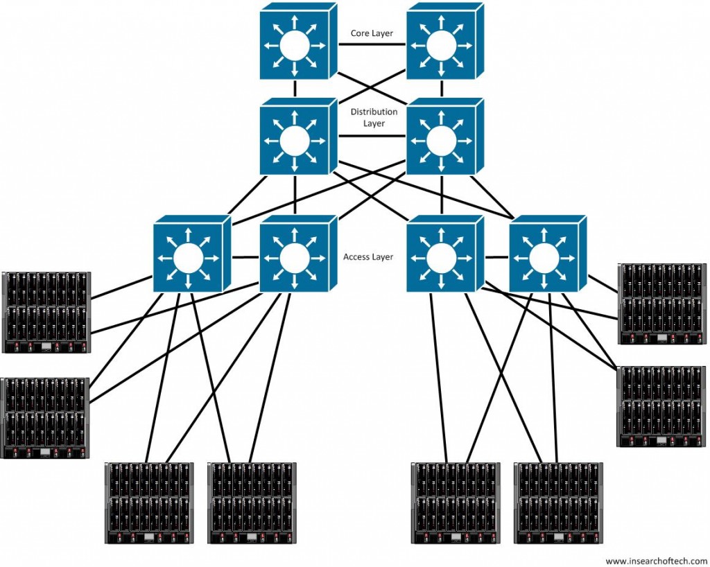
Take the following diagram for example:
 This should look somewhat familiar to most people. You have your standard 3 layers in the data center. Although only 4 blade enclosures are represented as connecting to each distribution switch, imagine that the number is 5 times as many. I didn’t want the drawing to get too crowded, so I took a few shortcuts. Imagine that this data center network is large enough to require multiple sets of access switches.
You have redundancy with this particular setup, but you also have a decent administrative burden to go along with it. You have to manage all of these switches. What are the options?
For those of you familiar with Cisco’s solutions, you have some options in terms of VSS, vPC, and Fabric Path to help ease that burden. If you use Arista switches, you can use MLAG. With Brocade, you have VCS. I suspect Open Fabric from Extreme Networks will do the same thing, but I am not real knowledgeable on that solution. Last, but certainly not least, is Juniper. With Juniper’s QFabric, you essentially turn your data center into one gigantic switch. Of course, you could almost make the same argument with the Cisco Nexus 7/5/2 play. QFabric just seems a bit more interesting to me than the Nexus 7/5/2 solution.
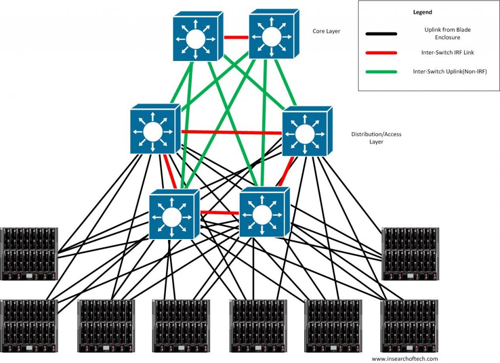
All of those are valid options. Some are easier than others to implement. Some are cheaper than others to implement. Some make more sense than others. However, this post isn’t about any of those other vendor solutions. It is about HP’s IRF. In light of that, let me put my blinders on and look at the solution to the data center problem above from HP’s perspective. You take the 3 tiers with a ton of blade enclosures on the access side and make it look like this:
Now I admit that this looks a bit more confusing, so let me point out a few things:
- All switches shown are HP A12500 series switches.
- You don’t have to use uplinks from each blade enclosure to each of the 4 distro/access switches. I put 4 links from each BE to show what COULD be done. It doesn’t mean that must be done that way.
- This diagram shows 2 logical switches instead of what would normally be 6. The top 2 form the core tier and the bottom 4 form the access/distribution layer. I could have used other terms like “spine” instead of the usual layer terminology, but decided against it since I don’t want to muddy the waters any further.
- The green uplink connections could be scaled back a lot more than they are configured as now. Again, this is designed to show what COULD be done and not what MUST be done.
- The red lines are the IRF links that the physical switches use to communicate with each other using LACP. Each chassis has 2 logical IRF ports on board and each logical IRF port can have up to 8 links in it. That means you can get an 80Gbps IRF connection between 2 switches in theory.
- Since there are only 2 logical IRF ports on a switch, you cannot have 4 switches meshed together for IRF purposes. It has to exist as a ring, hence the diagram above.
The design goal for the diagram above is two-fold. First, there is an incredible amount of redundancy built in. Of the 4 switches in the IRF group providing access/distribution layer type services, you can lose 3 of them and still function. Granted, that assumes that all of the blade enclosures have links to each of the 4 switches. Using redundant uplink/switch modules in whatever blade enclosure you are using makes this a realistic scenario. Second, the administrative burden in this scenario is minimal since you only have 2 logical switches to administer. As configurations within a core switch aren’t going to change that often, you essentially have to worry about making changes on 1 logical switch.
Of course, not everything is as bright and shiny as it seems. There are some tradeoffs/considerations when it comes to IRF. These are the ones I am aware of, but there may be more:
- Non-scaling MAC and ARP tables. – When you combine 4 A12500’s into a single logical switch, you don’t get an exponential increase in MAC and ARP table resources. You are confined to the limitations of a single A12500. While this might seem like a big deal, it may not be depending on the number of hosts within your data center. Every environment is different.
- Additional uplink ports required for IRF. – If you are going to connect 4 A12500’s to each other using 10Gbps interfaces, you will need to allocate double the amount you normally would if you were simply connecting to another A12500 for 2 switch IRF linking. Not a huge deal considering the amount of slot real estate on the A12500’s, but something to consider.
- Long distance links. – You can extend IRF links with distances of up to 70km/43.5mi, but there COULD be some issues with losing the link. Split brain detection with IRF is good as there are 3 methods it can use to determine ultimate up/down state. I am never a fan of “stacking” outside of the wiring closet on the edge and IRF is in effect, stacking. I have to agree with Ivan Pepelnjak on this one. Just because you can, doesn’t mean you should. However, this option is there and can be used as a way to extend L2 across data centers.
Closing Thoughts
My goal in this post wasn’t to discuss each and every feature when it comes to IRF. It was really to point out that you can run IRF across 4 12500 series switches. This is a pretty big deal in my opinion. In the largest data centers around the globe, this isn’t a big deal as 4 probably isn’t enough for them. However, I would wager that the overwhelming majority of data centers(ie 90% +) could benefit from 4 chassis IRF on the 12500 series switches. The software to make this happen is supposed to be available in November of 2011, so hopefully by the time you are reading this, it is either available, or a few short weeks from availability.
I should point out that I have no real world experience using IRF. I simply have an academic understanding of it. At least, I assume I have an academic understanding. As always, if I am incorrect, please feel free to point out my inaccuracies or flat out heresy.
***Disclaimer – HP sent me to Interop NYC in October of this year. I was not obligated to write about them at all. I’ve been trying to write something up about IRF since October, but have been too busy with my full time job to get it done. What you just read took about a month and a half to write and several revisions to come up with scattered in 10-15 minute increments of work. If I ever was a shill for HP, I am not a very timely one. 😉


Hey Mat,
One quick correction which seems to be going around lately. IRF is limited to 2-4 ONLY on the chassis platforms. On the stackables ( like the 5820 ToR 10 GB switch, or the 5800 gig which support MPLS/VPLS ) it will actually stack up to nine. Some of the lower end models also have a lower stacking limit.
Right now, it’s safe to say IRF can stack somewhere between 2 and 9, platform specific. To get the limit on the device you’re looking at, just check the data sheet.
One other thing which I’m not a fan of is the comparison between IRF and VPC. Since VPC has no later 3 awareness (afaik) it must rely in l3 protocols like hsrp or vrrp for failover, resulting in MUCH higher reconvergence times in the case of a l3 outage. IRF has some insane numbers like .7ms when configured properly ( NSF/gr, etc…)
Great post! It’s nice to see you writing.its been awhile… 🙂
@netmanchris
Chris,
Thanks for mentioning the non-chassis numbers. I didn’t bother with them since my main interest is in the big boys(12500’s). The Cisco 3750 and Juniper EX4200’s can stack that much as well. Actually, Juniper can go up to 10 I believe. Brocade also has a recent stackable switch. Not a whole lot of difference there except that Cisco is tied to a stacking cable and Juniper can use fiber instead of their stacking cables if you so desire.
Yes, the L3 is a differentiator. Thanks for pointing that out!
Matthew
The split-brain detection methods seem fairly centered around local connectivity (direct links, detection through connected switches) , which might hinder a long distance scenario.